One footprint, two types of of fuses
Sometimes, flexibility is key. Like when you’re not sure what parts to use on your electronics project. I’ve been fascinated by PCB footprints that allow different parts on the same footprint. Like differen packages of the same microchip, to have an easier time in case of shortages.
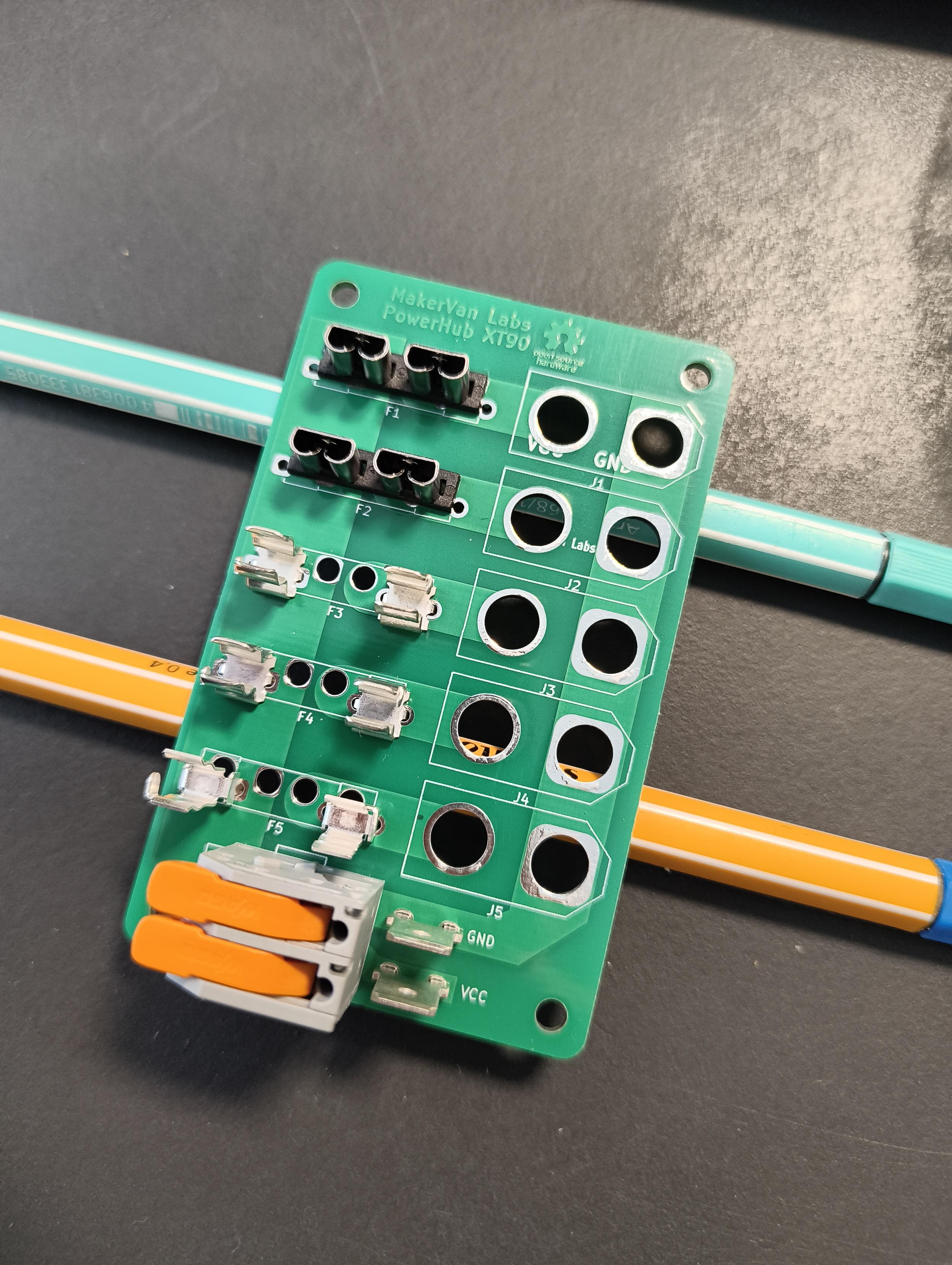
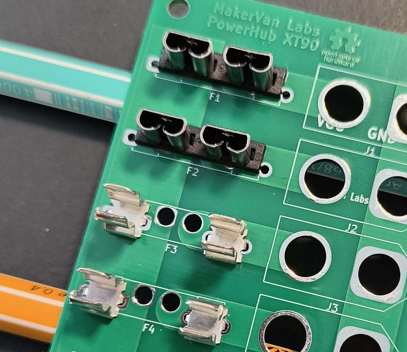
When designing the XT90 Powerhub, a small DC distribution board, I was not sure what type of fuse I might want to use for it, those small glas tubes (5x20mm), or the kind you might know as car fuses (ATO), which have almost the same size. So I decided to avoid that design decision all together and design the PCB to that I can choose when actually building the board for each individual use case.
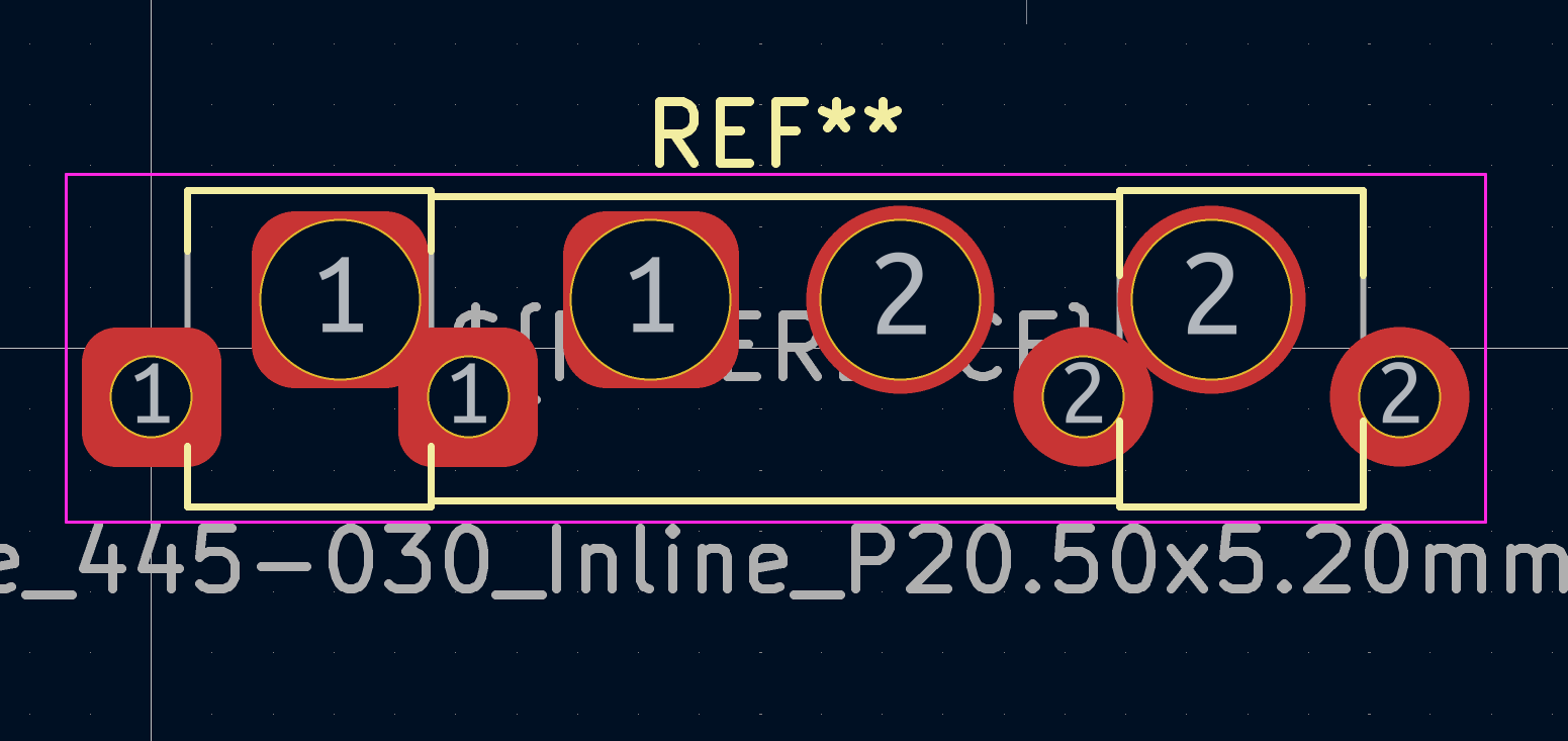
The footprint is essentially a merger of the two original footprints. As we have only two pins on each fuse, this is a very simple example, but it felt like a good start to get started on the concept.
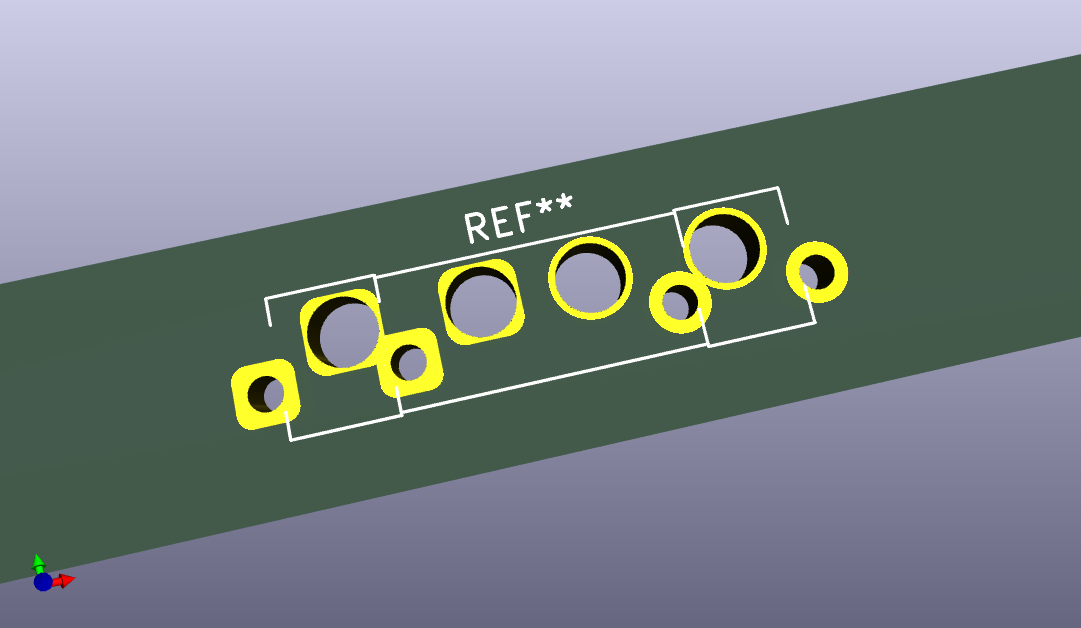
You might notice there’s a small offset between the two footprints. Initially, they were both in line with each other. Checking the final design against the manufacturing capabilities of the PCB manufacturer, it turns out some holes were too close together for their specifications. After some though, I just moved them apart on the vertical axis, just enough to have enough clearance to be back in their specs. When the part is mounted, you hardly notice the offset.
To use it in your project, you can find the source file on Codeberg.